- DIPTRACE LAY OUT TRACE STRAIGHT ZIP FILE
- DIPTRACE LAY OUT TRACE STRAIGHT MANUAL
- DIPTRACE LAY OUT TRACE STRAIGHT PC
- DIPTRACE LAY OUT TRACE STRAIGHT FREE
Ravi VermaĭEPARTMENT OF ELECTRICAL AND ELECTRONICS ENGINEERING BANSAL INSTITUTE OF SCIENCE & TECHNOLOGY, BHOPAL (M.P)ĬERTIFICATE I hereby certify that the work which is being presented in the B.E. Head of the electrical & electronics Department:Mr. ―3 Phase Fault Detection’ Department of electrical & Electronics (EX) SUBMITTED TO:. If I screwed anything up and wasted $19 I'll report that so others can avoid the same mistakes.Bansal Institute of Science &Technology Kokta, Anand nagar, Bhopal (M.p) JLCPCB says 2 days for the boards, then whatever time DHL takes, so I'll probably have them in a couple of weeks. So 10 boards including shipping is $19.00. The board is roughly 2.5"x 2.25", and the cost for 10 is $2.00.not each, total.
DIPTRACE LAY OUT TRACE STRAIGHT ZIP FILE
Then I clicked on the JLCPCB icon and was taken to their site where I dragged the Gerber zip file to it, answered a few questions mostly accepting default answers, and placed the order. Once I was satisfied with the layout, I created the Gerber files which just required clicking on a menu item.

DIPTRACE LAY OUT TRACE STRAIGHT PC
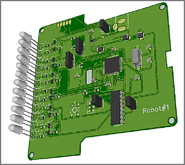
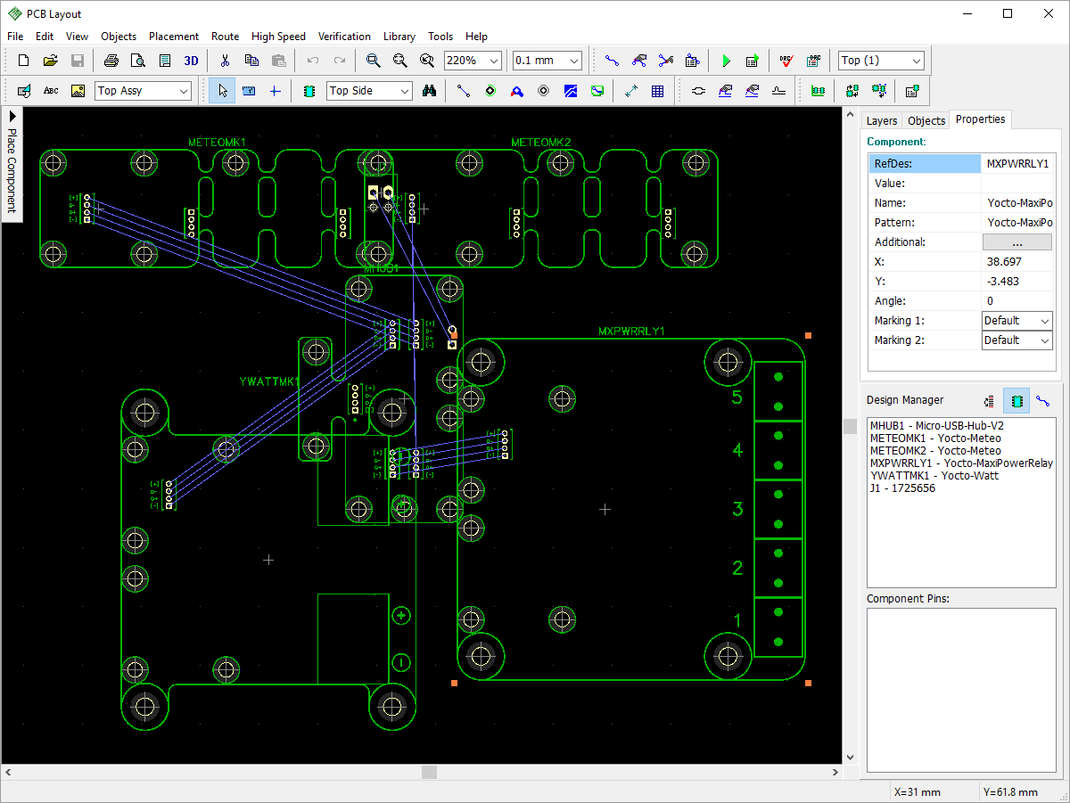
Once the schematic was finished, I switched to the PC board layout mode, placed the components, ran the traces where the lines indicated they should be, added input and output headers, text to identify things, and mounting holes. All of the components were contained in existing libraries, so that made it even simpler. Admittedly what I wanted was very simple.nodeMCU, relay, and a few discrete components, but the process was VERY simple. I might or might not not run them completely, but I plan the path and how it will end up.įor anyone interested in this topic, I used the site to first draw the schematic, and then design the PC board. But when I start laying down traces I first start with power and ground. Usually I look at ranging the parts so the connected parts fit together as cleanly as possible. The whole path from whatever starting point you have, along with the return path back to the start. When you have an input or output, follow the path that the current will need to take. It gives the allusion that as long as you are connected to the ground net, that everything is ok. One of the worst things as far as pcb design is the ground symbol. And that often is as much work as just running the traces yourself. Auto-routers are ok if you put enough effort into working with the rule set. I suggest staying away from autorouting a board. I tend to make my pads extend further beyond the part in order to give me some pad that I can touch a soldering iron to when I am soldering the part.
DIPTRACE LAY OUT TRACE STRAIGHT MANUAL
This is great in order to get higher part density in the design but it doesn't make it easy for manual assembly or rework. Most surface mount footprints are made as small as the part allows. Make sure the dimensions are correct, the pads and traces how you would want them. When using someone's library part, check it over carefully. Odds are you probably will use pretty standard parts. Look to see if they have the ESP module you want to use.


Whatever package you look at, take a look to see if there are libraries for parts you plan to use. Parts for the schematic, and then the footprint for the pcb layout. So I had borrowed the USB dongle a few times but haven't got too far due to lack of time.Īssuming you pick up the program's operation pretty fast, the part that can suck a lot of time is making parts.
DIPTRACE LAY OUT TRACE STRAIGHT FREE
I wanted to use a free package but I just hated to have to learn a new program for the little I plan on doing. I think it was about $5000 for the basic level with one license. It is a commercial package and hate how much we have to pay for it. I have used Pads for over thirty years now. I expect they know what to expect from the output of that program.Ī part of my job at work is to do the pcb layout for my designs. My thought is that you may have one less issue as far as board files and formats. I would try that if you are going to use JLC-PCB.


 0 kommentar(er)
